

Week 15
Week 15
Networking and Communication
Assignment:
Design and build a wired and/or wireless network connecting at least two processors.
FTDI cable for serial: RS-232
Tx-Transmits
Rx-Recieves
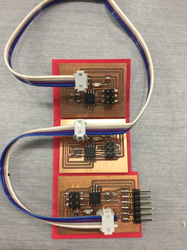
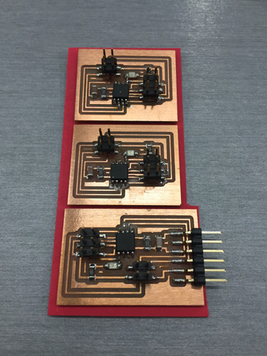
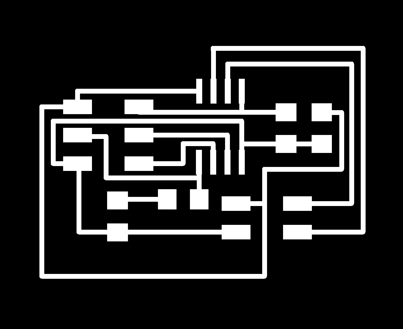
Serial Bus:
Bridge Board- runs transmit/receive to header
Node Board- power/ground/transmit/receive
Multiple connectors on one cable
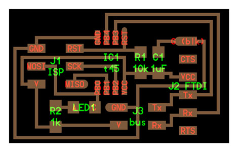
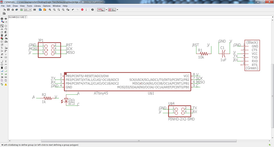
I designed my board after the Serial Bus boards from the weekly assignment page: http://academy.cba.mit.edu/classes/networking_communications/index.html
Bridge: http://academy.cba.mit.edu/classes/networking_communications/bus/hello.bus.45.bridge.png
Node: http://academy.cba.mit.edu/classes/networking_communications/bus/hello.bus.45.node.png
C: http://academy.cba.mit.edu/classes/networking_communications/bus/hello.bus.45.c
Makefile: http://academy.cba.mit.edu/classes/networking_communications/bus/hello.bus.45.make
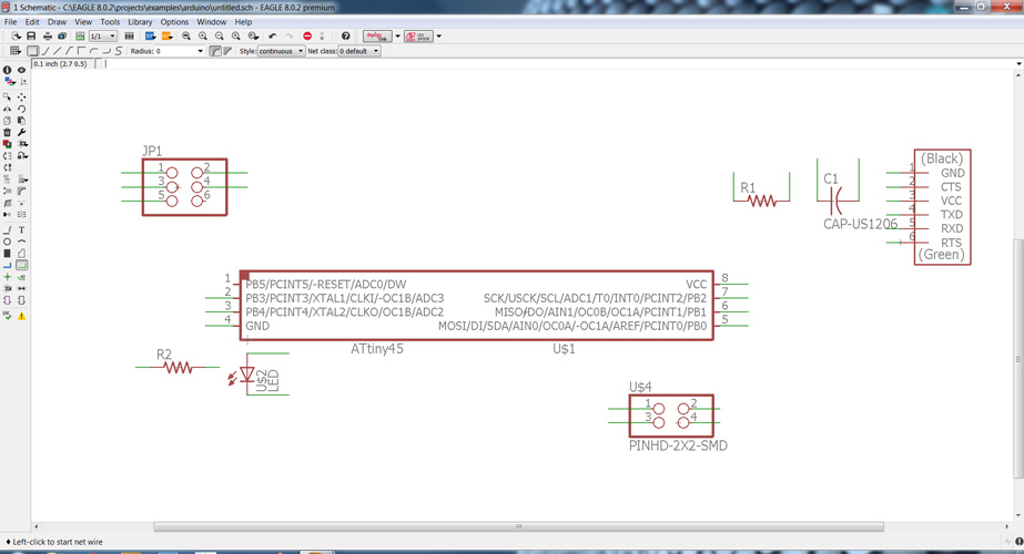
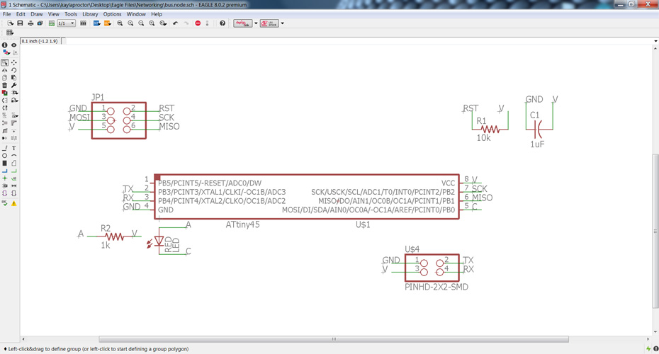
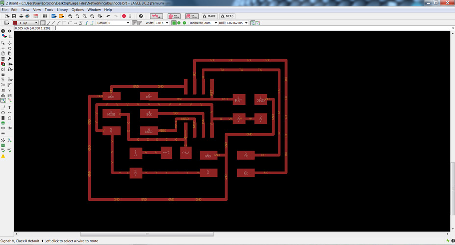
After assessing the components and what I would need I went to Eagle to start designing the board. I made the bridge board first.
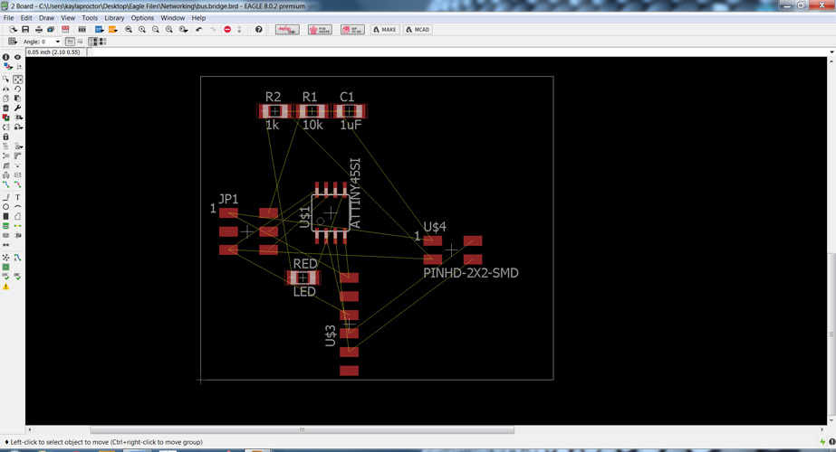
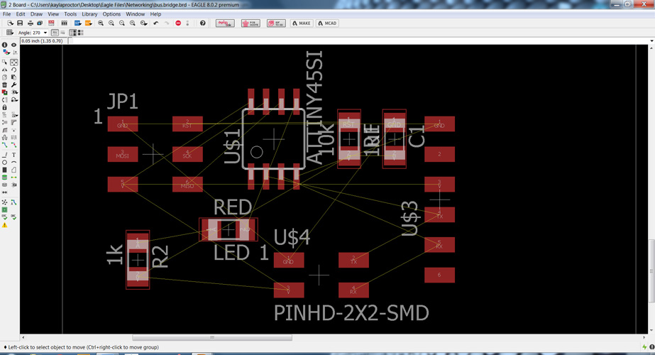
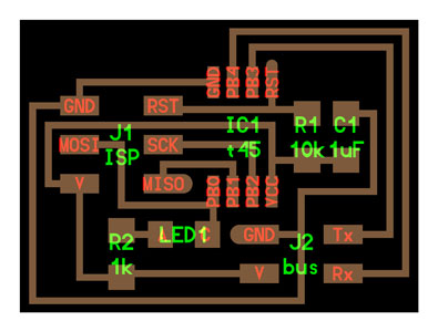
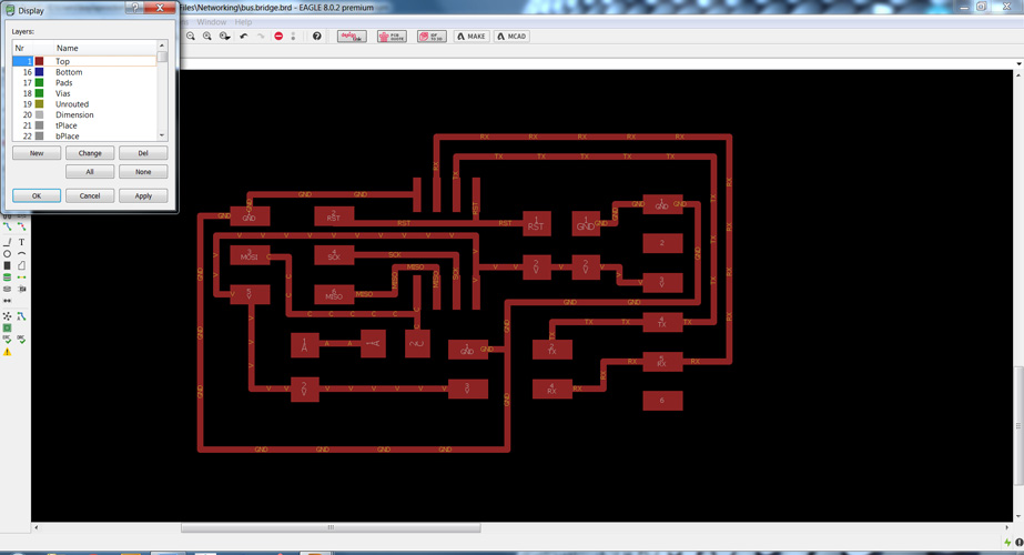
Since the node boards are so similar I did a save as and changed the name and removed the header to easily design them.
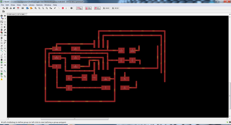
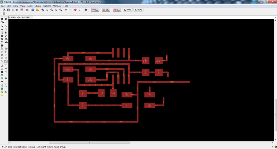
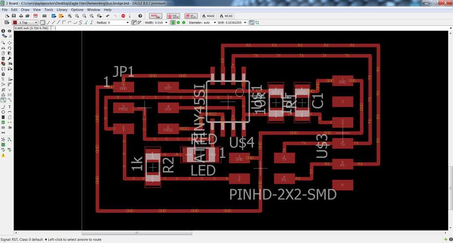
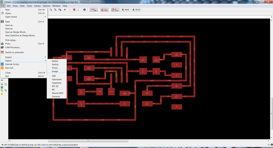
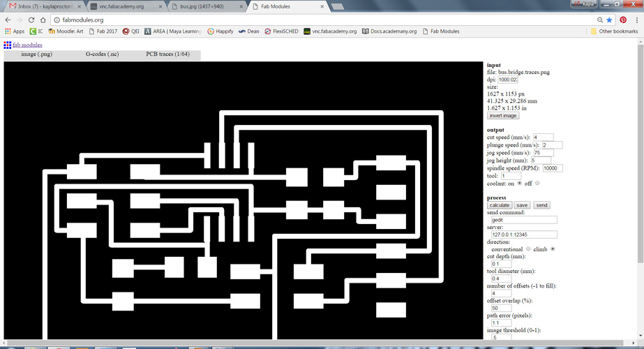
Then I turned off all layers except the top and exported as an image-PNG
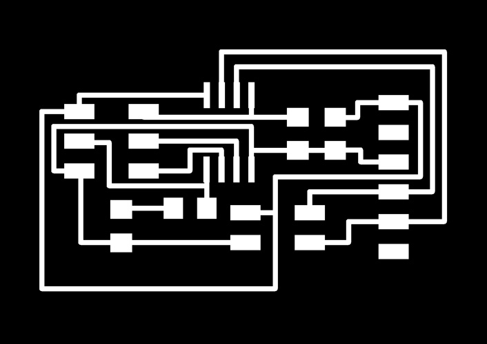


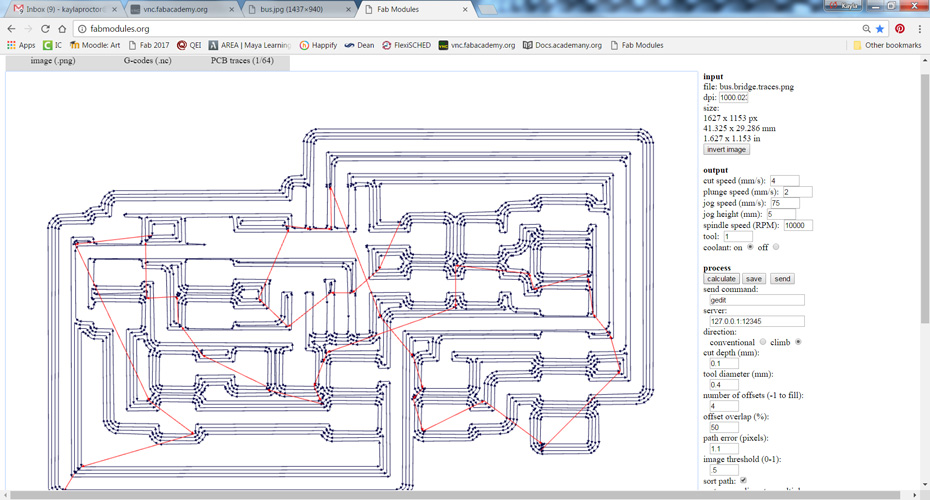
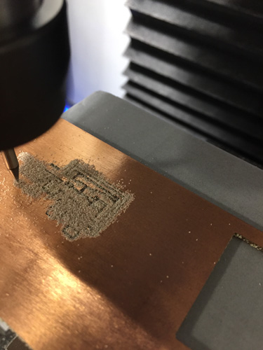
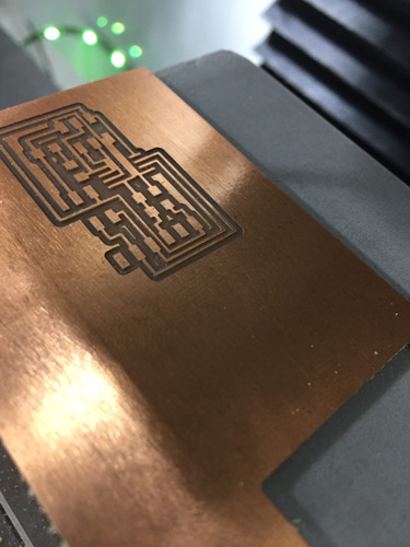
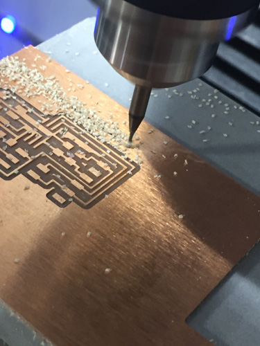
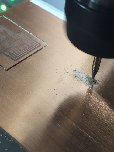
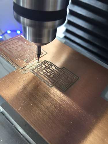
I used the fabmodules.org to convert the traces/outlines to G-codes.
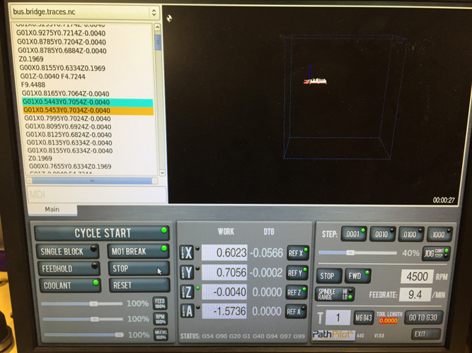
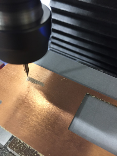
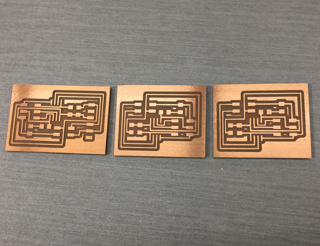
Then I went to our CNC mill, zeroed the machine and then ran the code. I first ran the Bridge board and outlines. Then repeated the same steps twice to make the Node boards and their outlines.
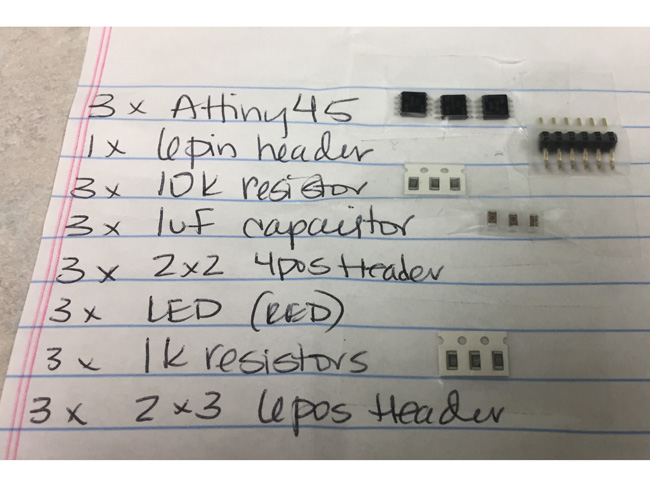
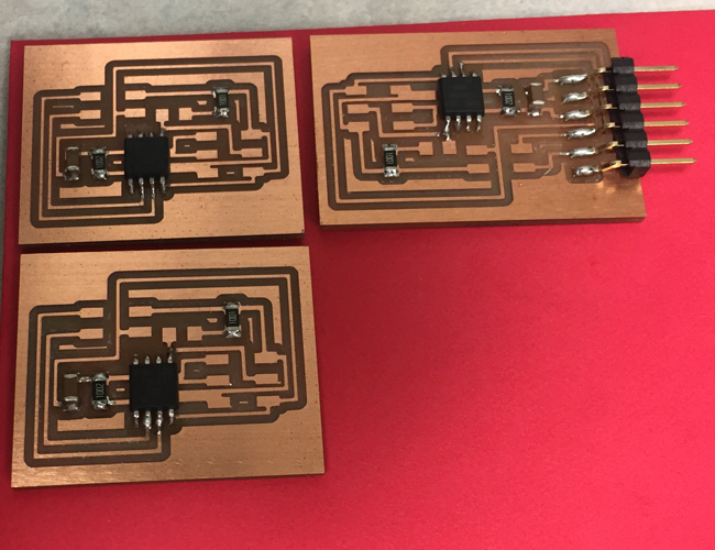
I then compiled all of my parts and referenced my parts lists and soldered to complete my boards.
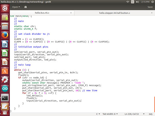
Off to the Linux computer to flash the boards and run the program.
In the Terminal I ran: cd ~/Desktop/networking (to access where I had saved the makefile and c file)
I changed the line in the make file to include the Atmel_ICE programmer which I have been using for all of my projects.
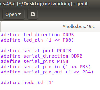
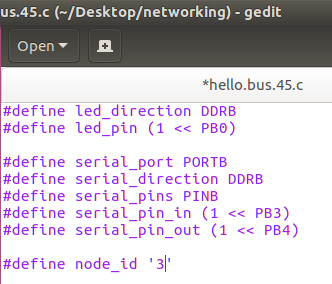
Then I opened the C file and identified the bridge board which I had set up with the FTDI and Atmel_ICE as #define node-id ‘1’.
Then typed in the Terminal: make
Then: make program-ice
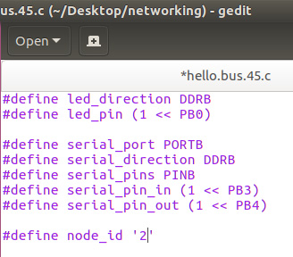
I then repeated the process by hooking up node ‘2’ and node ‘3’ and changing the #define node-id to match those boards as well. For those boards I ran make and make program-ice as well.
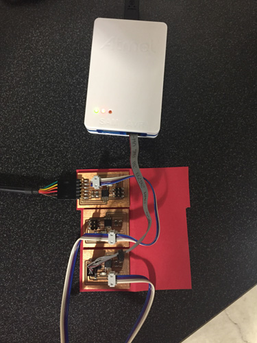
Once the boards were flashed I removed the Atmel_ICE and only had them connected by the FTDI cable and the 4 wire cable that connected the 3 boards.
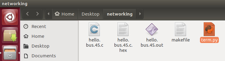
I downloaded the term.py (by googling it and finding the file) and added it to my networking folder that I had already cd’d into.

In the Terminal I typed: python term.py /dev/ttyUSB0 9600. This opened the terminal to send to the nodes. All boards flashed. When the window opened I typed 1-2-3 and each board flashed twice to show that it was communicating and passing through the “network”. I then made the video below and continued to type in numbers to see the red LEDs light up on the corresponding boards.
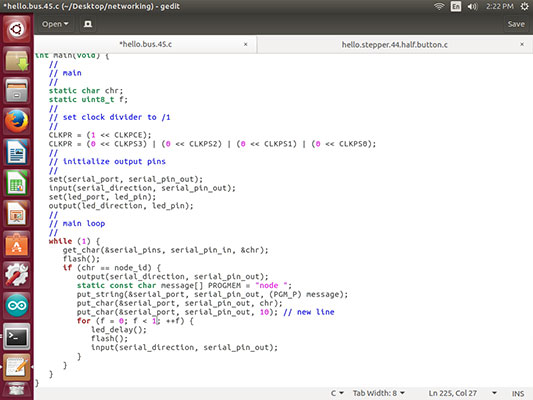
Once I had this part complete I went back into the C Code and altered it to show a different light blink. I have added the file in the project files below. I followed the steps above to reflash the board and you can see the difference in the video.

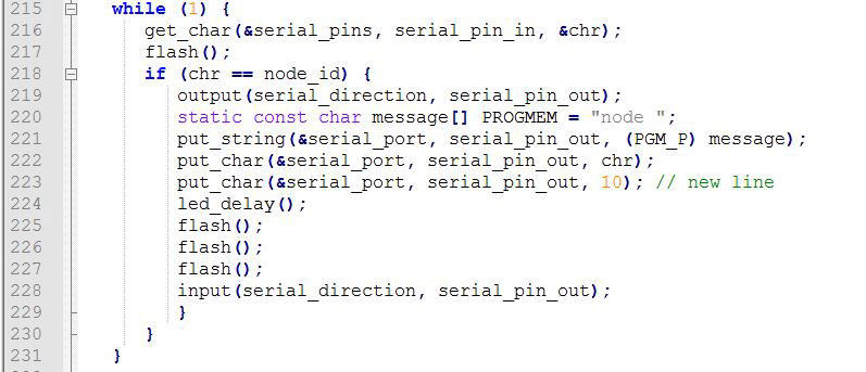
I then went in to try a more sophisticated code. In order to get the lights to blink a different amount of times to respond to each node I altered the c file with the node '1' again and then added the static uint8_t f. Then added a for statement and defined f to match the node number below to make the light blink the same number of times as the node. hello.bus.45.c modified blink amounts

Week 15 Photos